

Upright Mounted Specs:
- Meet ANSI, BIFMA, DIN and GSA Structural Standards.
- Earthquake Proof Tube Over Tube Design.
- Heaviest Grade Laminate Used.
- Painted Adjustable Brackets.
- Shelf is Is Steel Reinforced.
- Adjusts in 1" Increments.
- Weight Capacity: 150# Distributed Weight.
- Under-Shelf Bracket and Steel Top Reinforcement are Included.
- ! Order Uprights Separately.
! The wider the shelf, the weaker the shelf - even with our strong tubular understructure. To counter this, we recommend eight and ten foot shelves be supported with an additional upright in the center, Then put it up.
- Standard: ESD laminate top with grounded frame under standard (insulating) powder coat.
- Upgrade: Entire frame, legs, and structure coated with static-dissipative ESD paint (10⁶–<10⁹ Ω to ground).
- Spec: Fits the ANSI/ESD S4.1 worksurface guideline of ≥1×10⁶ to <1×10⁹ Ω and the ANSI/ESD S20.20 requirement of <1×10⁹ Ω to ground.
- Result: Top, frame, and legs all function as one ESD-controlled workstation, not just the worksurface.
Electrostatic Discharge (ESD) Control Testing
Electrostatic discharge (ESD) control testing was performed in accordance with ANSI/ESD S20.20-2021, using the ANSI/ESD STM4.1-2017 test method for worksurfaces.
The objective of this testing is to verify that the ESD paint and steel structure meet the required Resistance to Ground (RtG) limits so the bench is suitable for use in an Electrostatic Protected Area (EPA).
Product Under Test:
ESD workbench with ESD-finished steel structure.
Scope and Approach
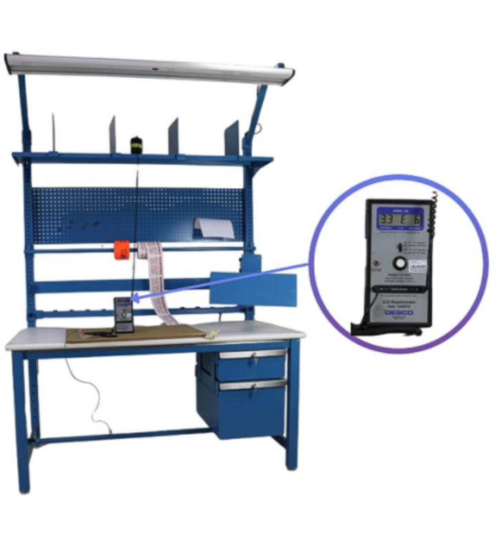
Testing was carried out on the ESD workbench at representative contact points along the painted structure, following the discharge path from the ESD paint through the frame to the grounding connection point. This validates that the bench provides a controlled, compliant path to ground across the structure for use in EPA environments.Tools Used
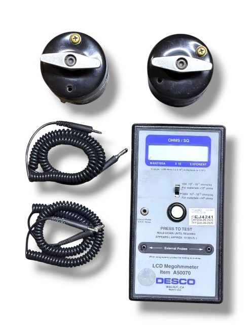
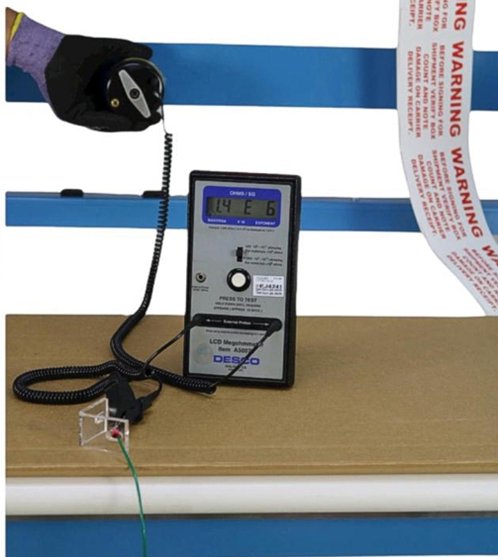
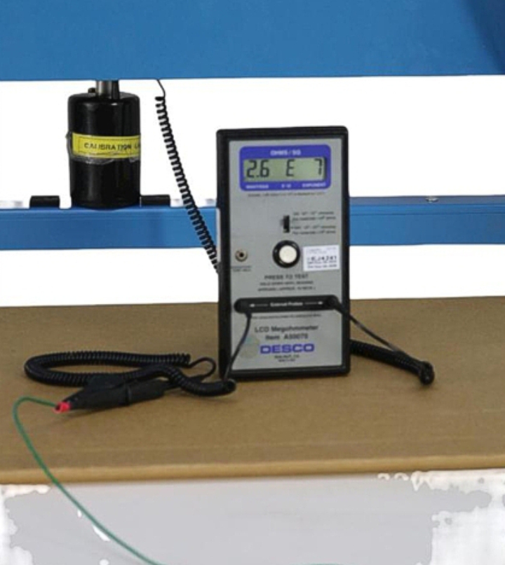
To perform the resistance measurements, we used a DESCO LCD Megohmmeter (Item A50070), a meter designed for testing ESD worksurfaces and grounding paths.
Measurements were taken by connecting one terminal of the meter to the ground reference point and placing the test electrode on each selected point of the painted structure.
Note: According to ANSI/ESD S20.20-2021, the maximum allowable Resistance to Ground (RtG) for ESD worksurfaces in an EPA is < 1.0 × 10⁹ ohms.
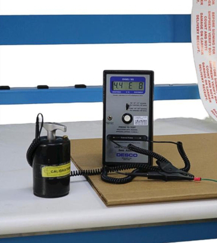
PROCESS & RESULTS: Work Surfaces
Measurements were taken from the main worksurface and shelving to the ground point. Both surfaces showed excellent conductivity.
| Test Location | Result (Ohms) | Limit | Status |
|---|---|---|---|
| Worksurface Top | 4.4 × 10⁸ | < 1×10⁹ | PASS |
| Top Shelf | 3.3 × 10⁶ | < 1×10⁹ | PASS |
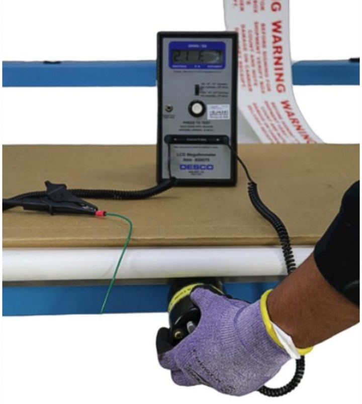
PROCESS & RESULTS: Accessories
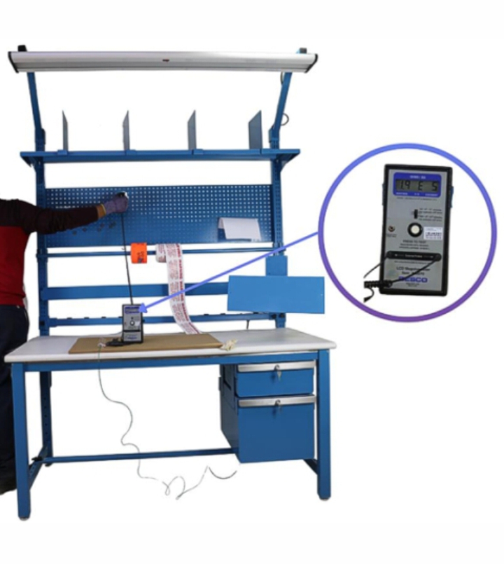
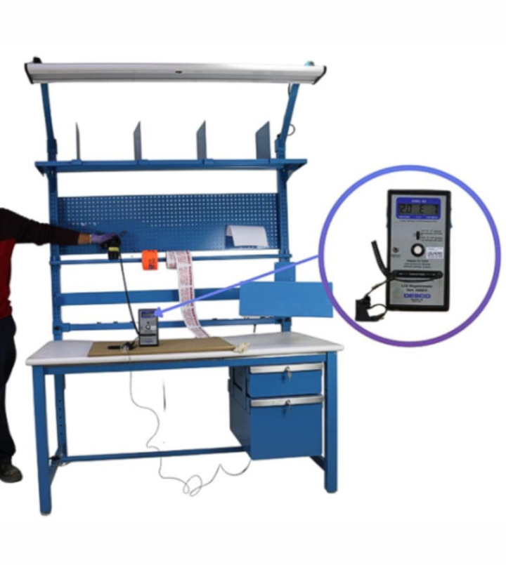
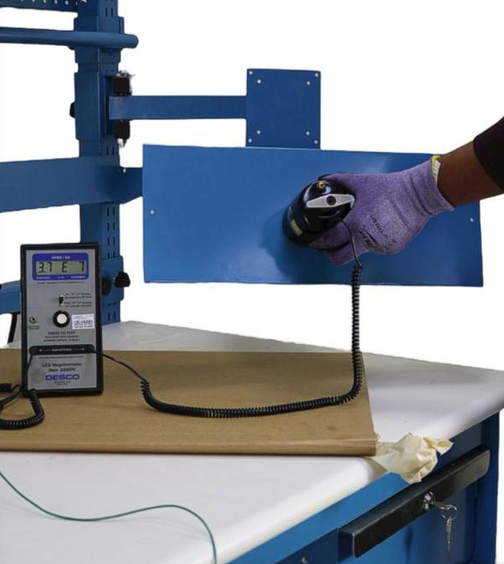
Vertical accessories and holders were tested to ensure the paint provides a path to ground throughout the structure.
| Test Location | Result (Ohms) | Limit | Status |
|---|---|---|---|
| Pegboard | 1.9 × 10⁵ | < 1×10⁹ | PASS |
| Roll Holder | 2.0 × 10⁷ | < 1×10⁹ | PASS |
| Bin Box Rail | 1.4 × 10⁶ | < 1×10⁹ | PASS |
| MHLK (LCD Monitor + Keyboard Holder) | 3.7 × 10⁷ | < 1×10⁹ | PASS |
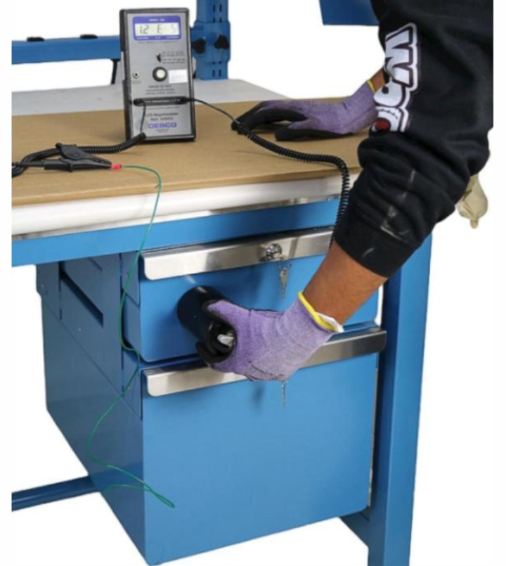
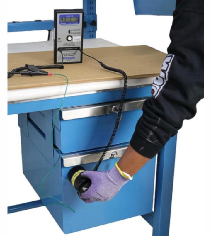
PROCESS & RESULTS: Storage & Ground
Drawers and the main frame were tested. All components passed, ensuring a safe discharge path for the operator and equipment.
| Test Location | Result (Ohms) | Limit | Status |
|---|---|---|---|
| Drawer 1 | 1.2 × 10⁵ | < 1×10⁹ | PASS |
| Drawer 2 | 4.0 × 10⁵ | < 1×10⁹ | PASS |
| Frame | 2.1 × 10⁷ | < 1×10⁹ | PASS |
| Power Strip | 2.6 × 10⁷ | < 1×10⁹ | PASS |
Conclusion
Testing demonstrates that the ESD workbench is in full compliance with the Resistance to Ground (RtG) requirements for structures and surfaces that come into contact with static-sensitive items.
- Final Declaration:The product meets the ANSI/ESD S20.20-2021 acceptance limit of < 1.0 × 10⁹ ohms RtG.
- Suitability: The ESD paint and finished steel structure are suitable for use in Electrostatic Protected Areas (EPAs) and provide a compliant foundation for an effective ESD control program.
Adjustable Top Shelf Assembly
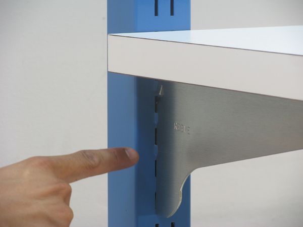
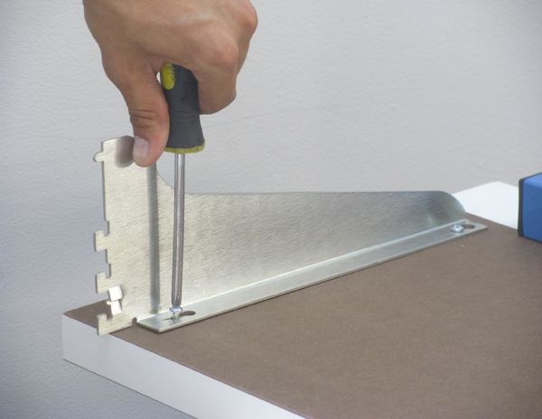
1. The shelf has two screws installed at each end. Position the brackets with their fingers facing away from the rounded edge of the shelf and the bent over bracket parts facing each other as illustrated below. Lower the bracket over the heads of the screws and slide the bracket toward the front of the shelf. Tighten the screws.
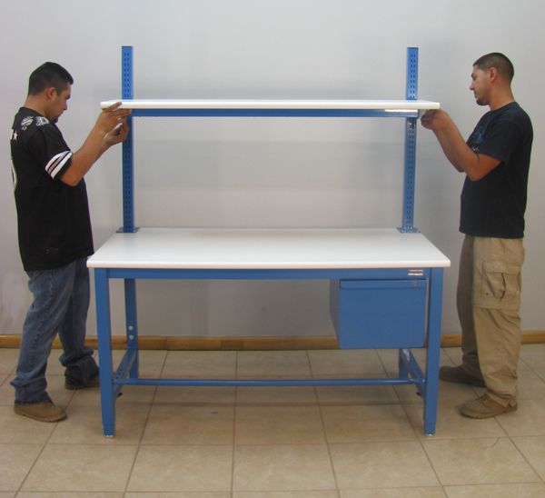
2. Two people are needed to slide the fingers into the slots on the uprights.
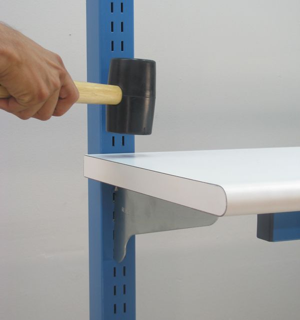
3. Tap the shelf top near the uprights to slip the fingers down into position. It doesn't take much of a tap, and can be done with a closed hand.
4. The finger spacing should look like this.